- If you have Dropbox enabled to automatically upload screenshots, disable that, as it appears to interfere (did for me on Windows 7)
- Open Snipping Tool and press ESC, so that the text says "Select a snip type from the menu [...]"
- Set up the shot you want, then hit Control + Print Screen
- Select the snip type you want and get the shot. The window you had open before will be frozen so you can move the mouse around now without losing hover text and drop down menus.
Since I discovered this, I've been taking the time to document things I learn to do in various software. The main reason is that often I come back later and can't remember some particular trick or button or whatever, and having a screenshot describing it is really nice.
So, here's a FreeCad tutorial along these lines. This version uses FreeCAD 0.14 (except for the first few screenshots, before I realized I should update my old version). You'll want to click on the images to view them at a more reasonable size. We'll be making a very simple square part with some holes. This tutorial goes through everything in detail and step by step, for those of you who find that kind of thing useful.
Step 0: Get FreeCAD
Get FreeCAD here.
Step 1: Start it up
Start up FreeCAD. Click on the top left button (circled below) to create a new project.

Step 2: Create a part
From the menu select "Part Design"

Create a sketch. Choose a plane for it. I chose the XY plane.

Step 3: Make a Rectangle and Add Constraints
I've marked the rectangle tool with an arrow below, in the top menu bar. It is a bit further right in FreeCAD version 0.14 due to some extra toolbars visible in this context by default. You may want to rearrange your toolbars at this point if they are too cluttered; I prefer to have multiple rows rather than a scrolling row. This follows the standard way you do this in most GUIs, just drag and drop.
Once the rectangle is created, you'll notice that four constraints have been created--two vertical and two horizontal. There are still four degrees of freedom in this sketch, as reflected in the text box on the left. The rectangle can still change position on the XY plane and change horizontal and vertical size.

Step 4: Add some constraints
To set the dimensions of this rectangle, use the horizontal and vertical distance constraints, circled below in blue. Before you click, you'll need to select either two points or a line. To select or deselect something, click on it (no need to shift click for multiple selection, regular clicking adds to selection). To deselect all, click on some blank space (the axis lines here are selectable items, but elsewhere on the grid will count). Selected items are in green (example below). Hovering over an item turns it yellow. Otherwise, lines are white and points are red.
Note the vertical axis here is marked in green, which makes it look like it is always selected. It is actually a slightly different shade of green than the 'selection' green.
Upon successfully selecting two points or a line, and adding a constraint, enter a value for it. You can change that later by double clicking the constraint in the menu on the bottom left. You can also delete it by clicking on it once to highlight it and then hitting the Delete key on your keyboard.

Go ahead and add constraints for both your vertical and horizontal dimensions. You can move around the numbers in the display by clicking and dragging on them, if they are getting too cluttered.
Now two degrees of freedom remain, because our fixed size rectangle can still move about this plane. So let's fix the position. Select two diagonally opposing points on the rectangle, then select the origin point. Click the symmetry constraint button (circled below) to create a constraint that will center our rectangle about the origin.

Step 5: Pad
Our sketch is fully constrained, congratulations. Hit the close button, which will switch the tab on the left from "Tasks" to "Model." You will see your sketch is here, and called Sketch. You may rename by right clicking on the name and choosing "Rename." If you click on the name twice, you'll go back into the edit sketch mode (again, click the close button to leave). If you click once, you will merely highlight it. This is what we want to do. Highlight your sketch and switch to the Tasks tab. Choose Pad from the Tasks menu. Enter a length to pad by and click "OK."
By the way: this might be a good time to save your work, so as a reminder, that is File > Save.
Step 6: Put a sketch on the top face
A quick aside: if you want to view our shape from different angles, you can use the buttons shown below. They will show up in both the "Part" and "Part Design" contexts.

Create a new sketch as before (in the Part Design context, in the Tasks tab). The issue though is it will be at the bottom of our padded box. We'd like it to be placed on the top plane of our box. So before doing anything else, close the sketch, and select the top plane of the box by clicking on it. It will turn green. Choose the "Map a sketch to face" button circled below. A menu will appear; choose the new sketch to map it to the face highlighted in green.

Step 7: Create a circle.
Next up we will create a circle that will later be pocketed into our part. Use the circle tool (circled below on the left hand side) and put it anywhere.
If you put it on top of other features you'll notice it might snap to create some constraints. You can delete them if you like, again that is by clicking on the listing for those constraints and hitting delete. Let's start with no constraints, just a circle.
Add a radius constraint (circled below on the right hand side). Now you will have just 2 degrees of freedom--the X and Y position of the circle.

Now make a second circle. We want this circle to be the same size as our first circle, so we'll use an equality constraint for that. This will be convenient because if we change our mind about the circle size, we only have to change it in one place later. The equality constraint is circled below, as well as the symbol that will show up on the drawing once it is in place.
Now we want to center both circles on the horizontal axis. For each circle, select the center point and the horizontal axis, then hit the vertical axis constraint (the I-shaped button, as before) and enter 0 for the distance.

The last thing to do with the circles is decide where we want them along the horizontal axis. Put in a horizontal distance constraint between the center of one circle and the origin. Then, to make the other circle be the same distance away but in the other direction, we'll use the symmetry constraint again. To do this, first select the centers of both circles, then select the origin, then hit the symmetry constraint button (which looks like a "><"). Our sketch should look something like this:

Step 8: Pockets
Close the sketch and select it (click on its name in the Model tab). Switch back to the Tasks tab and select Pocket. Enter a depth by which to pocket and hit OK. Now you should have pockets like this:

Note, you can always delete a pad or pocket by selecting it from the "Model" tab and pressing the Delete key on your keyboard. However, sometimes you've built up a sketch quite a bit and you delete something that other parts depend on, you can create issues. FreeCAD is pretty good but like pretty much every piece of software I've ever used, it is easy to crash. Save often and be careful when changing things that could break your design. I once corrupted a sketch (every time I tried to edit it, FreeCAD crashed). So save copies to serve as backups.
Step 9: More Pockets
Now I'd like to make some holes starting from the plane at the bottom of the circular pockets. I'd like these to go through the rest of the piece, to serve as holes for some mounting hardware. To do this, create a sketch ("Tasks" tab) and close it. Then again, use the "Map a sketch to face" button after selecting the bottom of one of the circular pockets. Double click on the sketch in the Model tab to get into edit mode. Add a circle and add a radius constraint to make it some size (smaller than the circles we made before).
I wanted to use the "Create an edge linked to external geometry" but it would not work with the circles from the previous sketch. I could not therefore create a constraint to make the new circle centers coincident with the old ones. So these circles are made just like the ones before. List of constraints:
Alright, the sketch is fully constrained now! Close it.

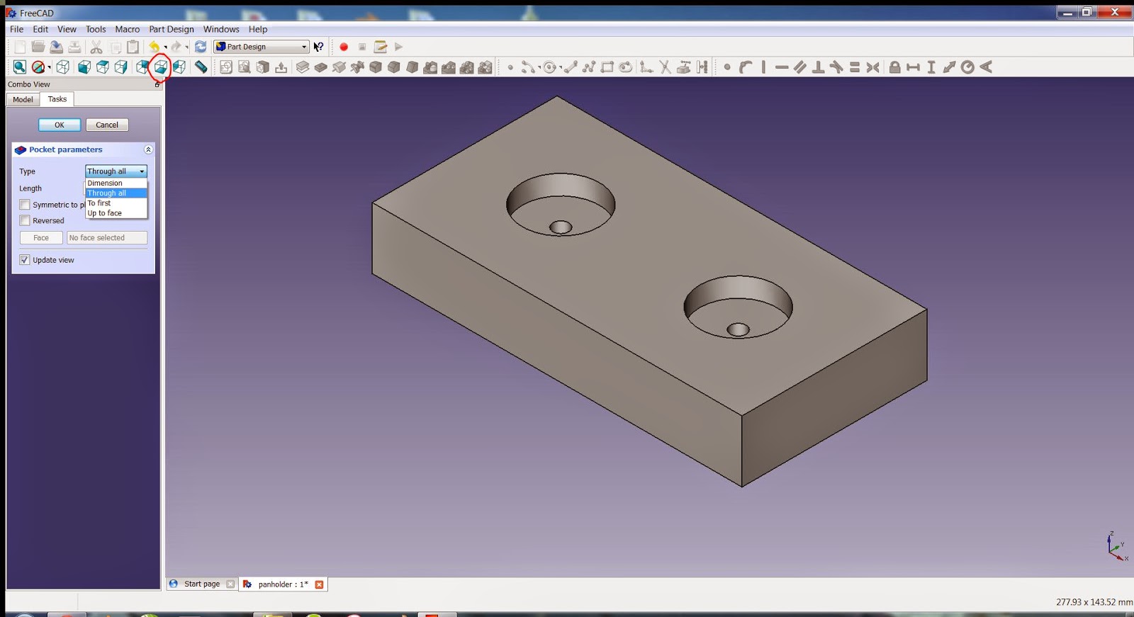
Now select the sketch and choose pocket. From the drop down menu choose "Through all." If you switch the view to the bottom view (circled) you can verify the holes go all the way through to the bottom. Hit the "OK" button.
Step 10: Fillet
I would now like to fillet this piece. Select the edges you desire to chamfer using Control + Click to add edges to your selection. Hit the fillet button (circled below) to fillet these edges.

So if that was your first tutorial, you now know how to:
Note, you can always delete a pad or pocket by selecting it from the "Model" tab and pressing the Delete key on your keyboard. However, sometimes you've built up a sketch quite a bit and you delete something that other parts depend on, you can create issues. FreeCAD is pretty good but like pretty much every piece of software I've ever used, it is easy to crash. Save often and be careful when changing things that could break your design. I once corrupted a sketch (every time I tried to edit it, FreeCAD crashed). So save copies to serve as backups.
Step 9: More Pockets
Now I'd like to make some holes starting from the plane at the bottom of the circular pockets. I'd like these to go through the rest of the piece, to serve as holes for some mounting hardware. To do this, create a sketch ("Tasks" tab) and close it. Then again, use the "Map a sketch to face" button after selecting the bottom of one of the circular pockets. Double click on the sketch in the Model tab to get into edit mode. Add a circle and add a radius constraint to make it some size (smaller than the circles we made before).
I wanted to use the "Create an edge linked to external geometry" but it would not work with the circles from the previous sketch. I could not therefore create a constraint to make the new circle centers coincident with the old ones. So these circles are made just like the ones before. List of constraints:
- Radius constraint on left circle
- Vertical constraint between left circle center and horizontal axis (0 distance)
- Horizontal distance constraint between left circle center and origin (same distance as used for bigger circles)
- Vertical constraint between right circle center and horizontal axis (0 distance)
- Symmetry constraint between left circle center, right circle center, about the origin
- Equality constraint between left circle and right circle (copies the radius of the left circle to the right)
Alright, the sketch is fully constrained now! Close it.
Now select the sketch and choose pocket. From the drop down menu choose "Through all." If you switch the view to the bottom view (circled) you can verify the holes go all the way through to the bottom. Hit the "OK" button.
Step 10: Fillet
I would now like to fillet this piece. Select the edges you desire to chamfer using Control + Click to add edges to your selection. Hit the fillet button (circled below) to fillet these edges.
So if that was your first tutorial, you now know how to:
- Create a fully constrained sketch
- Pad a sketch
- Pocket a sketch
- Chamfer/fillet along edges
No comments:
Post a Comment